Dave Weyer 3 Transistor Hendrix Fuzz
This is a 3 transistor Fuzz Face circuit designed by Dave Weyer for Jimi Hendrix.
Let you select between two independant fuzz/gain setting for a extremly wide range and fuzz is always on to color the sound.
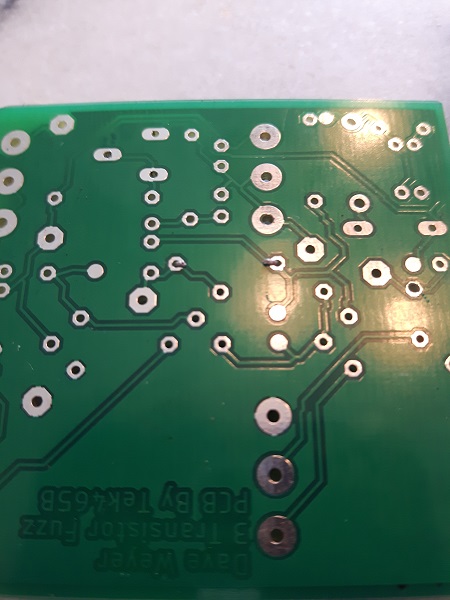
Bare PCB:

First clean the PCB using a solvent
Then install the small component first(resistors, diodes) but do not install the Zener and potentiometer yet!
I like to pre-bend the lead and use a nail cutter to trim the lead and i completly bend the lead to the PCB before soldering
Solder and install all the component(except the Zener and potentiometers).
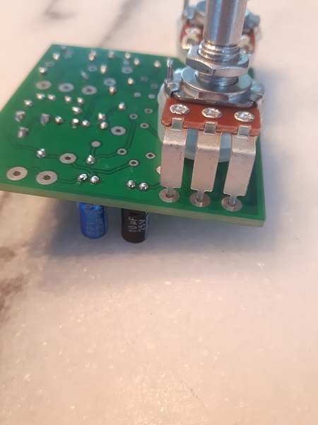
Start with the 5K volume and next the 1K fuzz potentiometer, also install the 2 power wires.
Leave a small gap as shown here
Now is a good time to clean the flux!
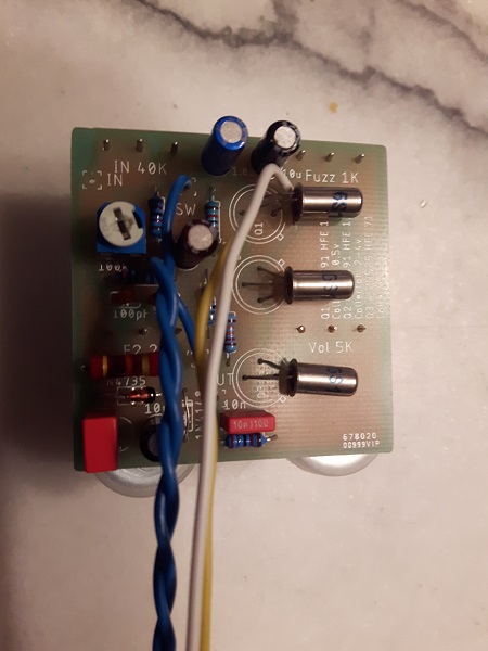
should look like this:
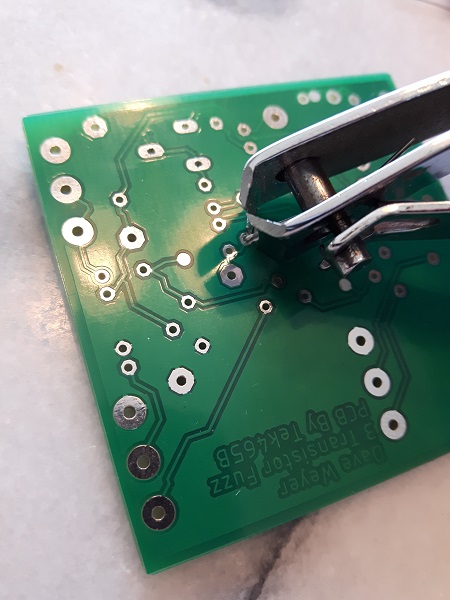
Next i used alligator clip to test for the correct Zener diode
You can see here at the red arrow where i attached my Alligator Clip
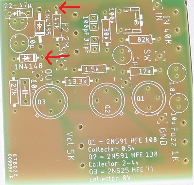
I set the bias trimmer fully clockwise and then set the 9V power on(yes there is no 2M and 40k potentiometer on the board, it do NOT matter for now). measured the Q2 Transistor Collector Voltage(using q2c, see picture below for test point location) i tried different zener until i got to around 3V.
Diode that worked for me was the 5.6Volt Zener and removing the 1N4148 Diode(using a wire jumper instead)
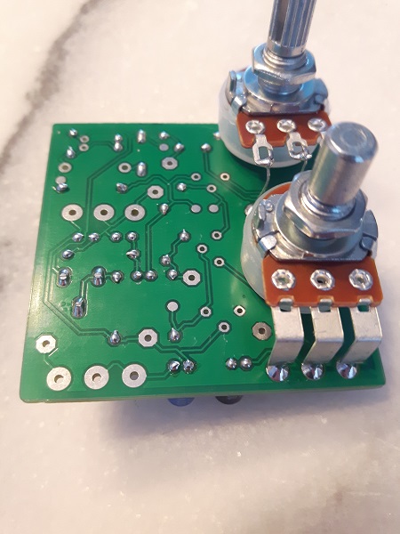
Now you can process to install/solder the potentiometers and the rest of the components on the board
For my own unit this is the transistor and bias setting that worked.
- Q1C = 0.46V, HFe = 80, Leakage = 166µA
- Q2C = 4.03V, HFe = 67, Leakage = 89µA
- Q3C = 7.59V, HFe = 67, Leakage = 113µA
- Bias Supply - Bias supply voltage = 6.09V
- Bias OUT - Bias with 5.6Zener and no 1N4148 = 1.59V
Test Point(used to check voltage with voltameter):
- Q1C = Transistor Q1 Collector Voltage(between 0.42-0.67 Volt)
- Q2C = Transistor Q2 Collector Voltage(between 2.65-4.32 Volt)
- Q3C = Transistor Q3 Collector Voltage(between 7.45-8.4 Volt)
- Bias Supply - Bias supply voltage(around 7.1 volt)
- Bias OUT - Bias voltage after the zener(With a 5.6 Zener diode should be around 0.82Volt)

PCB layout:

Black PCB layout true bypass:

Black PCB layout always on cancel switch:
.jpg "Black wiring NONBYPASS")
Download gerber files here (work with www.seeedstudio.com):
PCB Gerber
Dont forget to fix the transistor pin silkscreen error. They need to be inverted 180.
Here is the Kicad project and files and some libraries, so you can edit and make your own gerber files:
PCB Gerber
Here is the Schematic

Part List(Part number in green are for green PCB only, in Red are for Black PCB only and Black are for both PCB.):
| Value | Quantity | Tayda Number |
|---|---|---|
| 10uF | 2 | Nichicon: A-1799, Panasonic: A-4141 |
| 10nF | 1 | A-1549 |
| 1.82uF | 1 | Tayda do not source 1.8uF, so i use a 1uf (A-4179) and 820n (A-4139) in parallel. |
| 820nF | 1 | A-4139 |
| .22-.47uF | 1 | A-4163 A-4512 or A-4516 |
| 1uF | 2 | A-4179 |
| 33pF | 1 | A-525 |
| 100pF | 1 | A-531 |
| 1N4148 | 1 | A-157 |
| 1N4745 | 1 | A-101 and A-171. Order other value to get bias in "ballpark" |
| 1M Gain Pot | 1 | A-1652, A-1672 |
| 1k Fuzz Pot | 1 | A-1618, A-1841 possible replacement: A-1863 |
| 50k Input Pot | 1 | A-1626, A-1858 possible logarithmic replacement: A-1660 |
| 100k Trim Pot | 1 | A-2506 |
| 5k Vol Pot | 1 | A-1912 solder lug type, could not find pcb mounted, A-1659 |
| Knob | 3 for Green PCB, 4 for Black PCB | A-2832 |
| Knob Volume | 1 | A-322 |
| 1590B Enclosure | 1 | A-5158 |
| 9v Battery Clip | 1 | A-870 or A-656 |
| DPDT Switch | 1 | A-1868 |
| Mono Jack | 1 | A-4556 |
| Stereo Jack | 1 | A-5069 |
| SPDT Toggle Switch | 1 | A-4567(2 position, recommended) or A-2001(3 position, middle to disconnect feedback loop) |
| Resistor | 8 One of each | 12k, 82k, 13.3k, 1.5k, 47k, 27k, 30k, 1Meg |
| Transistor | 3 | Q1 = 2N591 HFe = 108, Q2 = 2N591 HFE 138, Q3 = 2N525 HFE 71 |
For the transistor you want the Beta to be like most fuzz face for Q1 and Q2, Q3 anything over 50 will be fine.
Look for late production PNP germanium with low collector capacitance.
Bitcoin donation:
Donate